This is a simple-one-afternoot project that I made to be able to open the office door.
Our office door is locked by a presence control (with fingerprint reader, keypad and NFC cards) which is connected to a cloud server and API service. So, to open the door with just a button I need two curl calls to the API service in that server (one for login and another for opening the door).
I love using Omega2 over other projects because has 3 mainly things: has easy built-in wifi, is linux and is cheaper than other things like arduino. Also it’s footprint is quite small.

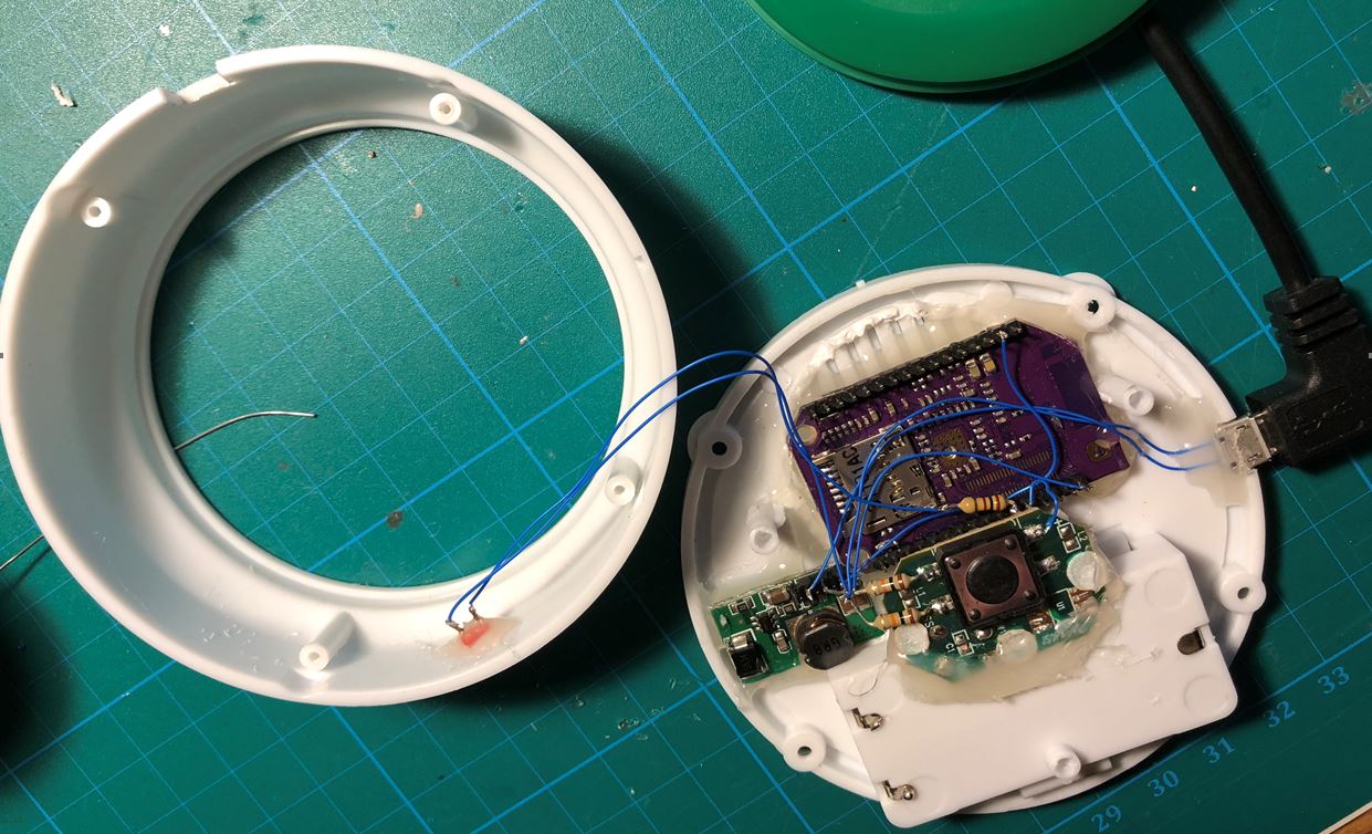
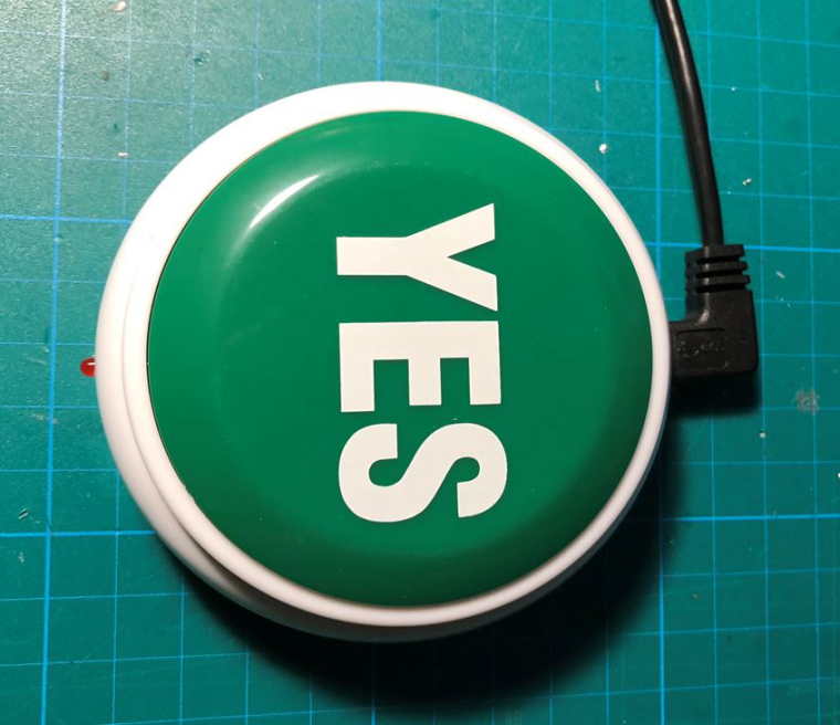
For the button, I searched over some sites looking for a big button with small footprint but was a futile search. I ended for a chinese repurposed button. This one had a speaker and said ‘Yes’ when pushed’.

I tore it down to fit inside the Omega2 main board, a small DC-DC step down 5v to 3.3v and a micro-usb connector for power. Also I put a small red led to show opening status. I reused the momentary switch soldering a pull-down resistors. Switch is on GPIO 17 and LED on GPIO 11.
Once everything is fit together comes time for a small code. I have 2 scripts. This one is a loop to read the gpio button:
#!/bin/sh

# Boton (Input)
fast-gpio set-input 17 > /dev/null 2>&1

# LED (Output)
fast-gpio set-output 11 > /dev/null 2>&1
fast-gpio set 11 0 > /dev/null 2>&1

# Bogus GPIO?
gpioctl dirout-low 16 > /dev/null 2>&1

while [ 1 ]; do

        # Get button status
        STATUS=`fast-gpio read 17|awk '{print $4}'`

        if [ $STATUS -eq 1 ]; then
                fast-gpio set 11 1  > /dev/null 2>&1
                # LED is light meanwhile the script 'open.sh' is being executed
                /root/open.sh
                fast-gpio set 11 0 > /dev/null 2>&1
        fi

        # Some sleep
        sleep 0.05
done
The other one has the 2 curl sentences:
#!/bin/sh
# Do login and save the cookie
curl -i -c cookie_door \
-H "Accept: application/json" \
-H "Content-Type:application/json" \
-X POST --data '{"name": "someUser","password": "somePassword","user_id": "700"}' \
"https://api.biostar2.com/v1/login" > /dev/null 2>&1
# Use the cookie to open the door (index 1)
curl -i -b cookie_door \
-H "Accept: application/json" \
-H "Content-Type:application/json" \
-X POST --data '{"door_id": "1"}' \
"https://api.biostar2.com/v1/doors/1/open" > /dev/null 2>&1
As a side comment about the ‘bogus GPIO’, I don’t get quite how works the GPIO in Omega2. Seems that GPIO 17 and 16 are somehow linked? I had to put 16 on dirout-low so 17 could work great.
Also I had to install GNU/sleep that accepts times <1s. This way doesn’t use too much CPU without having to sleep 1s that could cause missing push to the push button.
In the end the project is highly usable for almost everything as is a simple network enabled IoT button. Changing the ‘open.sh‘ script can make this project to use in a infinity uses.