Archivos en la categoría 'Cacharros'

Repairing a Nikon D80 with ERR message

Sábado, Diciembre 4th, 2021

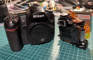
Initially introduced at $999 body only this was a prosumer camera back in 2006. Later years and up today photography comunity members started to report a ERR message in their cameras top display (in the shutter speed field). This error is commonly associated to the mechanical parts of the camera (shutter, diaphragm and mirror) being not properly in sync.

I have already fixed 3 cameras with these flaws. These cameras where brougth to me as for parts/teardowns so I decided to publish a small guideline on how to fix them.

Nikon D80 and the main mechanics

Nikon D80 and the main mechanics

Seems that this specific model of Nikon had two major flawn that made the mechanics out of sync. Maybe the fault comes from the design, maybe comes from quality control. The flawns are:

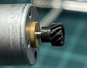
Main motor pinion gets broken. This makes the pinion too loose so the motor spins without transmiting it’s force to the mecanism and rotating in void. The main electronics detects no action in it’s sensors despite givin the command to spin the motor, hence produces the ERR message. This is fixable by carefully removing the pinion, putting a smal drop of SuperGlue in the motors shaft tip then pushing back the pinion.

Nikon D80 main motor pinion broken in half

Nikon D80 main motor pinion broken in half

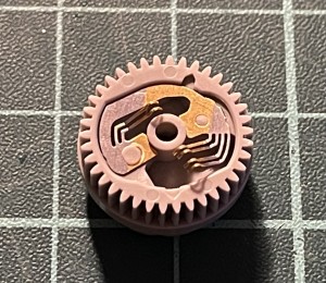
Mechanics encoder loses one brush fixing. The mechanic rotatory enconder is the electronics main sensor of the mecanics position and travel. It’s made of a gear that has a fixed brushes against a PCB board where makes it’s contact. The brushes are fixed by a plastic welding that brokes with passing time. The brushes then missaling or makes no contact at all. Electronics loses perception of the mechanics travel and position and then drops the fatal ERR message. This can be fixed with a small drop of superglue in the affected/broken plastic fixing (in this photo, the right side one).

Mechanics rotatory encoder with one broken/loose plastic fixing.

Mechanics rotatory encoder with one broken/loose plastic fixing.

I recommend to let dry the superglue at least 1  hour before trying the fix. You can start assembling the camera inmediatly but is best for all to let it totally dry before inserting a charged battery to try it out.

Any of these flaws renders the camera unusable. Fortunally both flaws are relative easy to fix, but both requires a lot of careful dissasembly to be able to get to the afected parts. I recommend to follow the help this Nikon D80 service manual and use a welder when the disassembly requires to unsolder some wires.

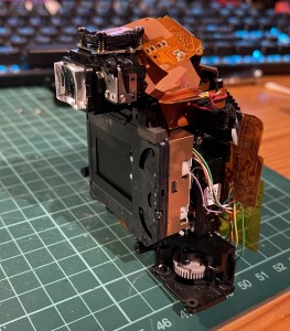
Nikon D80 main mechanics, motor removed. The main encoder can be seen below, being the grey gear.

Nikon D80 main mechanics, motor removed. The main encoder can be seen below, being the grey gear.

Apollo AGC DSKY Block II Front Plate

Viernes, Agosto 31st, 2018

This is a very clear photo of the front plate of the Apollo G&N Computer (AGC) Display and Keyboard (DSKY).

In this photo can been seen the segments that composed the display fonts because the wear ni a different color.

AGC DSKY Block II

AGC DSKY Block II

Broken Kindle 3

Lunes, Julio 8th, 2013

This is a donation of a friend as its not working. Actually this kindle 3 stop working when booting, hence the reason that shows the booting load bar.

broken Kindle 3 Front

broken Kindle 3 Front

I tried to search for onboard blown fuses but every single fuse I found was in good condition. After that I researched over internet and found that has a debug serial port. I tried to attach my usb to serial ttl converter with a little level shifter (kindle serial port works in 1.8v) but had no luck, not even a single character was shown in my Zterm :(

broken Kindle 3 Back Opened

broken Kindle 3 Back Opened

I wanted to install debian to see how the display could work and some few hack I’m thinking of but being the board pretty much dead (only seems to work for its battery charging) I decided to save it for parts as battery, case, metal frame, keyboard and display seems in good working conditions (although I’ve not been able to test them properly). If some generous reader has a kindle 3 with a broken display and he/she is willing to donate it to science I’ll be more than happy to pay the shipping.

LiPo Batteries Hacking and refurbishing

Domingo, Junio 30th, 2013

One of the difficult parts when prototyping is to find reliable power sources. Today is still hard to find the battery size we want to use because country exporting frontiers stops these chemical packages. Here I’ll show how to refurbish dead batteries by combining cells and protection circuits to preserve battery life.

An (almost) dead Apple MacBook Pro (17″) battery fell in my hands so I decided to tear it down to see if there was something profitable. Inside I found that the battery pack was composed with 6 individual cells, paired in 3 groups.

Apple Mac Book Pro 17" Battery Disassembly

Apple Mac Book Pro 17" Battery Disassembly

Seems that the third group had a small voltage difference between cells so they began discharge between them. This leaded both cells to die, condemning the entire battery pack.

Here can be seen the individual cells:

Batteries separated from the main board.

Batteries separated from the main board.

As can be seen the cells doesn’t have individual protection circuits witch are important to avoid discharge below 2.7v to preserve battery life.

I also came across with a small photo-frame that I bough just for hacking fun as is really a bad piece with almost no memory, no SD card expansion, 128×128 display and bad electronics. It cost me 1.99€ and the battery was drain dead from the first moment I opened the package.

Small and dead LiPo battery with the protection circuit.

Small and dead LiPo battery with the protection circuit.

It was inflated and reading 0.26v. Obviously battery couldn’t be rescued, but I salvaged the power cutting circuit. Here is the reverse side of the protection circuit board. Notice the polarity when soldering the LiPo cell and wires:

LiPo Battery protection circuit downside.

LiPo Battery protection circuit downside.

Once I soldered the protection circuit board to the Apple battery cell I ran some charging and discharging tests to ensure the assembly works fine and that power is cut at 2.7v:

Working Refurbished Battery

Working Refurbished Battery

Olympus E510 MOS Image Sensor

Viernes, Junio 28th, 2013

This DSLR came to me in a little market in Barcelona called Encantes, wich is open 3 days a week. At first I though it was a good thing to buy as the camera hadn’t any scratches or visual defects. It cost me 15€ so it was worth of buying it even if was broken.

Actually I tried to power up the camera by soldering a pair of cables to the battery attachment and feeding them with the 7.4v that its original batteries supply. After a few tries an multimeter measures I ended with a diagnose of broken power supply board. It costs about $40 to replace it but I’m not totally sure about if the rests of components will be properly working, plus the camera is 10Mpx, made in 2007 and has smaller 4:3 image sensor format, wich is poorly on high ISOs, so I decided to tear it down.

Olympus E510 MOS Image Sensor

Olympus E510 MOS Image Sensor

The MOS image sensor (big center colored square) is mounted over 3 frames. The first, image sensor frame moves in vertical axis meanwhile the second frame moves in horizontal axis. The third and outside frame is fixed in the camera. This conforms the IS (image stabilization) system of this camera that works regardless the lens you use on it. The bad thing about image sensor stabilization is that stabilizes image only for the final photo and live view, leaving the image unstabilized when looking in viewfinder and light/autofocus sensors.

Overall, is a really nice technology piece as the frames are moved with ultrasonic motors.