Archivos en la categoría 'Hardware'
DFP-34X-2C2 ZX279125 (ZTE Chipset) firmware Dump
Jueves, Abril 20th, 2023Available as a download here.
This is the mtd partition map:
# cat /proc/mtddev: size erasesize namemtd0: 00800000 00010000 “whole flash”mtd1: 00040000 00010000 “uboot”mtd2: 00130000 00010000 “kernel0″mtd3: 00130000 00010000 “kernel1″mtd4: 00010000 00010000 “others”mtd5: 00010000 00010000 “parameter tags”mtd6: 00060000 00010000 “usercfg”mtd7: 00270000 00010000 “rootfs0″mtd8: 00270000 00010000 “rootfs1″
Some hardware information:
/ # cat /proc/cpuinfo
Processor : ARMv7 Processor rev 1 (v7l)
BogoMIPS : 1196.03
Features : swp half fastmult edsp
CPU implementer : 0×41
CPU architecture: 7
CPU variant : 0×4
CPU part : 0xc09
CPU revision : 1Hardware : ZX279125
Revision : 0020
Serial : 0000000000000000
/ # cat /proc/meminfo
MemTotal: 21420 kB
Repairing a Nikon D80 with ERR message
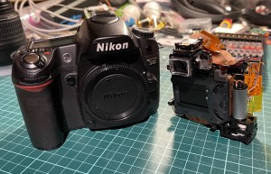
Sábado, Diciembre 4th, 2021Initially introduced at $999 body only this was a prosumer camera back in 2006. Later years and up today photography comunity members started to report a ERR message in their cameras top display (in the shutter speed field). This error is commonly associated to the mechanical parts of the camera (shutter, diaphragm and mirror) being not properly in sync.
I have already fixed 3 cameras with these flaws. These cameras where brougth to me as for parts/teardowns so I decided to publish a small guideline on how to fix them.
Seems that this specific model of Nikon had two major flawn that made the mechanics out of sync. Maybe the fault comes from the design, maybe comes from quality control. The flawns are:
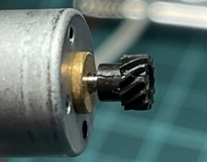
Main motor pinion gets broken. This makes the pinion too loose so the motor spins without transmiting it’s force to the mecanism and rotating in void. The main electronics detects no action in it’s sensors despite givin the command to spin the motor, hence produces the ERR message. This is fixable by carefully removing the pinion, putting a smal drop of SuperGlue in the motors shaft tip then pushing back the pinion.
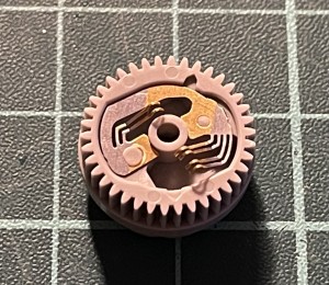
Mechanics encoder loses one brush fixing. The mechanic rotatory enconder is the electronics main sensor of the mecanics position and travel. It’s made of a gear that has a fixed brushes against a PCB board where makes it’s contact. The brushes are fixed by a plastic welding that brokes with passing time. The brushes then missaling or makes no contact at all. Electronics loses perception of the mechanics travel and position and then drops the fatal ERR message. This can be fixed with a small drop of superglue in the affected/broken plastic fixing (in this photo, the right side one).
I recommend to let dry the superglue at least 1 hour before trying the fix. You can start assembling the camera inmediatly but is best for all to let it totally dry before inserting a charged battery to try it out.
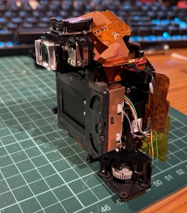
Any of these flaws renders the camera unusable. Fortunally both flaws are relative easy to fix, but both requires a lot of careful dissasembly to be able to get to the afected parts. I recommend to follow the help this Nikon D80 service manual and use a welder when the disassembly requires to unsolder some wires.
SYPHCOM: CO2 meter
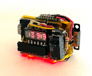
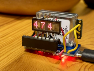
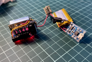
Lunes, Agosto 16th, 2021This is my last week project: a Simple Yet Powerful Handheld CO2 Meter. SYPHCOM (name in progress ..)
The use for a portable CO2 meter is to be able to measure air quality in closed spaces (i.e. the office). The higher the number (usually above 1200~1500) the worst ventilation, which means higher chances to get
the Covid-19.
With this is possible to know when is time to open the windows and ventilate.
It’s main guts are:
- Arduino Pro Micro, Leonardo Atmega32u4 based.
- SenseAir S8 LP CO2 sensor.
- Vintage HP HDSP-2000 ceramic LED matrix display, manufactured week 20 year 1984. NOS.
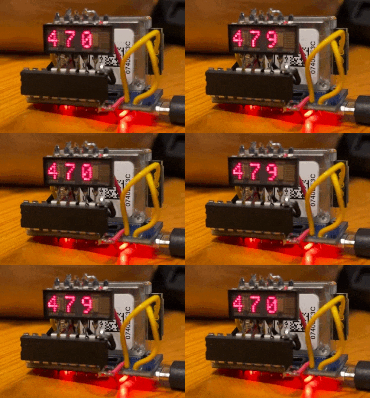
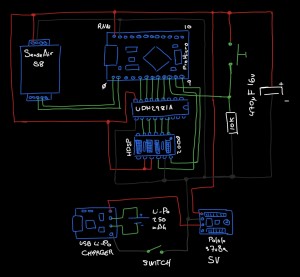
The capacitor stands for when the CO2 sensor does a read cycle (every 2s): both the display and the SenseAir S8 uses so much power that you can see the display and leds in the Arduino Pro Micro sighly dim off when powered from standard USB 0.5A when a read is made in the SenseAir CO2 Sensor. Without the capacitor, the arduino can’t stand for the display refresh and does a glitch in the display.
Also there’s a UDN2981A source driver to drive the columns in the HDSP-2000 display and a small momentary press button with 10K pull down resistor to launch sensor callibration if pressed on powerup (use with caution!!).
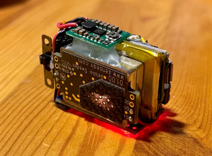
The components that makes it portable are:
- Lithium battery charger (Like this one).
- Recycled Li-Po cell (250mAh)
- Pololu s7v8a adjustable step-up DC-DC (adjusted to 5V).
- Switch.
I use the same components to make projects portables. The good thing about the pololu s7v8a is that it is both a step-up and a step-down DC-DC converter. This is handful if a project work 3.3v as it will give 3.3v always even if the battery is reading 3.0v. Unfortunally the recicled 250mAh battery is not much for the power needs so only lasts 30m on thi battery cell.
In the video the leds seems to be dimmer than they really are because of the high light, but actually they are pretty much visible.
Overall all makes a nice looking portable and easy to use CO2 meter and Covid prevention tool in closed spaces.
Omega2+ minidock and Oled custom enclosure.
Jueves, Septiembre 10th, 2020I’ve had this Omega2+ with minidock and soldered Oled SDD1306 lying around naked and decided to make a 3D printed custom enclosure for it.
Both halves snaps together to keep it closed.

