Archivos en la categoría 'Electrónica'

Expired RSA SecurID Token revival (guerrilla hack)

Lunes, Enero 25th, 2016

I had lying around an expired RSA SecurID with the typical blank display only showing a small 3 in the right.

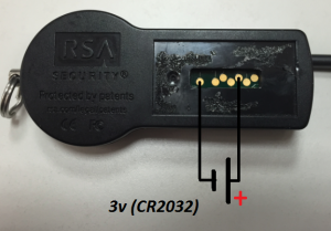
Looking for some info about expired tokens I found an old topic at flickr (original URL here) where Travis Goodspeed managed to revive one the tokens with a simple trick: apply 3v for a second in two of the pads behind the protective plate.

Here is the diagram:

Expired RSA SecurID Token Revival Diagram

Expired RSA SecurID Token Revival Diagram

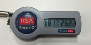
Here the revived Token:

Expired RSA SecurID Token Revived

Expired RSA SecurID Token Revived

The token was expired since november 2011 but still got battery to keep working.

I Haven’t tested if token still is valid to autenticate against RSA daemon after revival.

Broken Kindle 3

Lunes, Julio 8th, 2013

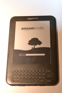
This is a donation of a friend as its not working. Actually this kindle 3 stop working when booting, hence the reason that shows the booting load bar.

broken Kindle 3 Front

broken Kindle 3 Front

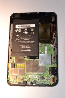
I tried to search for onboard blown fuses but every single fuse I found was in good condition. After that I researched over internet and found that has a debug serial port. I tried to attach my usb to serial ttl converter with a little level shifter (kindle serial port works in 1.8v) but had no luck, not even a single character was shown in my Zterm :(

broken Kindle 3 Back Opened

broken Kindle 3 Back Opened

I wanted to install debian to see how the display could work and some few hack I’m thinking of but being the board pretty much dead (only seems to work for its battery charging) I decided to save it for parts as battery, case, metal frame, keyboard and display seems in good working conditions (although I’ve not been able to test them properly). If some generous reader has a kindle 3 with a broken display and he/she is willing to donate it to science I’ll be more than happy to pay the shipping.

LiPo Batteries Hacking and refurbishing

Domingo, Junio 30th, 2013

One of the difficult parts when prototyping is to find reliable power sources. Today is still hard to find the battery size we want to use because country exporting frontiers stops these chemical packages. Here I’ll show how to refurbish dead batteries by combining cells and protection circuits to preserve battery life.

An (almost) dead Apple MacBook Pro (17″) battery fell in my hands so I decided to tear it down to see if there was something profitable. Inside I found that the battery pack was composed with 6 individual cells, paired in 3 groups.
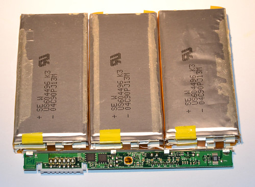
Apple Mac Book Pro 17" Battery Disassembly

Apple Mac Book Pro 17" Battery Disassembly

Seems that the third group had a small voltage difference between cells so they began discharge between them. This leaded both cells to die, condemning the entire battery pack.

Here can be seen the individual cells:
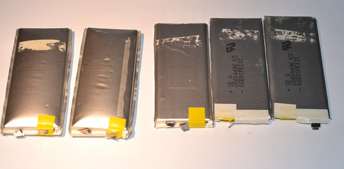
Batteries separated from the main board.

Batteries separated from the main board.

As can be seen the cells doesn’t have individual protection circuits witch are important to avoid discharge below 2.7v to preserve battery life.

I also came across with a small photo-frame that I bough just for hacking fun as is really a bad piece with almost no memory, no SD card expansion, 128×128 display and bad electronics. It cost me 1.99€ and the battery was drain dead from the first moment I opened the package.
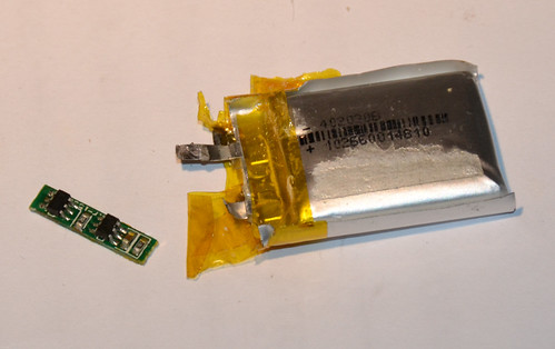
Small and dead LiPo battery with the protection circuit.

Small and dead LiPo battery with the protection circuit.

It was inflated and reading 0.26v. Obviously battery couldn’t be rescued, but I salvaged the power cutting circuit. Here is the reverse side of the protection circuit board. Notice the polarity when soldering the LiPo cell and wires:
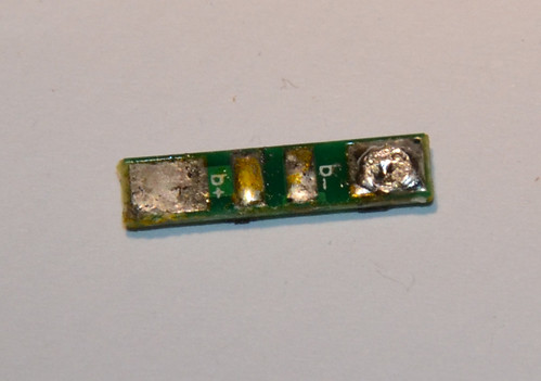
LiPo Battery protection circuit downside.

LiPo Battery protection circuit downside.

Once I soldered the protection circuit board to the Apple battery cell I ran some charging and discharging tests to ensure the assembly works fine and that power is cut at 2.7v:
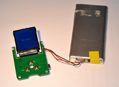
Working Refurbished Battery
Working Refurbished Battery
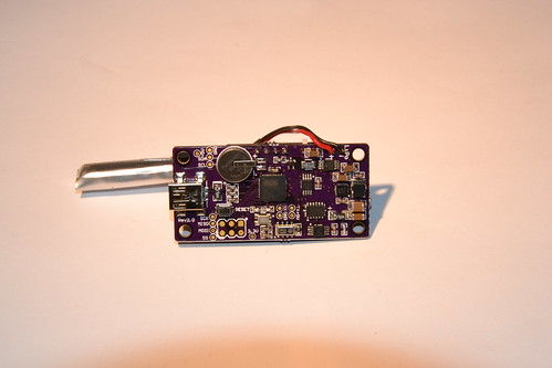
Arduino Sensor Board plus PongClock

Sábado, Junio 15th, 2013

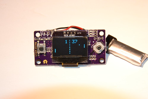
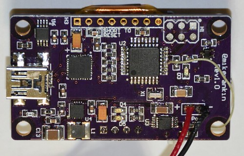
This tiny sensor board was solely designed by Mike Rankin, a friend that help me to bring life to a real custom GPS board. This time he was looking for a multi purpose board to develop anything.

Sensor Board Main display Side Showing Ponglock

Sensor Board Main display Side Showing Ponglock

Feature list:

  • I2C Bus to save pins for future use.
  • 128×64 OLED I2C Display: let’s draw anything
  • Momentary switch on left and cross plus center buttons on right (total 6 input buttons)
  • Arduino Leonardo based: USB for anything.
  • Temperature sensor (I2C)
  • Barometer sensor (I2C)
  • Accelerometer sensor (I2C)
  • Real Time Clock (I2C) plus backup battery.
  • Switched power supply.
  • LiPo charger.
  • Tiny design: let’s make portable projects.
Sensor Board Main Component Side

Sensor Board Main Component Side

I couldn’t resist temptation.. I ported the pongclock code from Rob Parrett to this tiny board. Here is the result:

Hardware is open hardware, you can obtain anything on Mike’s web or you can buy it directly from Tindie. Custom pongclock code can be downloaded from here.

Update: I fixed 3 bugs in the original code to fix pong game behavior to be as accurate as possible, like the scoreboard, ball missing and properly change of hours.

GPS Toy Hardware version 2

Jueves, Junio 6th, 2013
Update: If you want one for real it is now for sale at Mike’s Tindie page here.
Update 2: I made a 3D printed enclosure for this hardaware. You can find more here.

About 9 months ago one Hackaday reader dropped some comments about compiling the source I published here a year ago and some troubles. After that, Mike and me kept talking and things turn out that he was PCB developer, so we though we could make together GPS cube version for real.

Together we developed a schematic and Mike built all himself several prototypes until we finally came with a (almost!) final version. So, here we are, one year after first release:

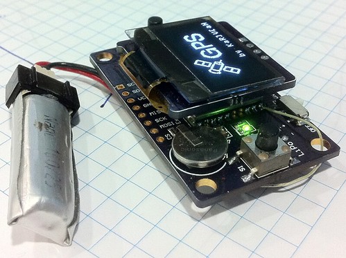
GPS Cube version 2

GPS Cube version 2

This version has several features:

  • Everything is packed together in a single board.
  • Better GPS: we switched to MT3339 PA6H instead old SirfStar III EM-411
  • We added TMP75 I2C temperature sensor.
  • The display PCB is also custom to run 3.3v
  • Everything runs 3.3v: GPS, display, FTDI, TMP75 and atmega328p is now running 8MHz, Battery lasts longer.
  • Expansion header with SPI and I2C: the board ca be used as development board for any other projects with displays or GPS.
GPS Toy Hardware Rev1.0

GPS Toy Hardware Rev1.0

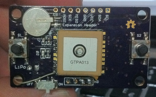
New GPS Board back

New GPS Board back

All the hardware was designed and developed by Mike Rankin (probably will go to Tindie) meanwhile I developed the software.