Publicado el 28th Junio, 2013 por KaRMaN. Archivado en Cacharros.
Leido 262,499 veces. 528 comentarios archivados.
This DSLR came to me in a little market in Barcelona called Encantes, wich is open 3 days a week. At first I though it was a good thing to buy as the camera hadn’t any scratches or visual defects. It cost me 15€ so it was worth of buying it even if was broken.
Actually I tried to power up the camera by soldering a pair of cables to the battery attachment and feeding them with the 7.4v that its original batteries supply. After a few tries an multimeter measures I ended with a diagnose of broken power supply board. It costs about $40 to replace it but I’m not totally sure about if the rests of components will be properly working, plus the camera is 10Mpx, made in 2007 and has smaller 4:3 image sensor format, wich is poorly on high ISOs, so I decided to tear it down.
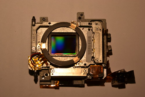
Olympus E510 MOS Image Sensor
The MOS image sensor (big center colored square) is mounted over 3 frames. The first, image sensor frame moves in vertical axis meanwhile the second frame moves in horizontal axis. The third and outside frame is fixed in the camera. This conforms the IS (image stabilization) system of this camera that works regardless the lens you use on it. The bad thing about image sensor stabilization is that stabilizes image only for the final photo and live view, leaving the image unstabilized when looking in viewfinder and light/autofocus sensors.
Overall, is a really nice technology piece as the frames are moved with ultrasonic motors.
Publicado el 15th Junio, 2013 por KaRMaN. Archivado en Arduino, Electrónica.
Leido 729,218 veces. 459 comentarios archivados.
This tiny sensor board was solely designed by Mike Rankin, a friend that help me to bring life to a real custom GPS board. This time he was looking for a multi purpose board to develop anything.
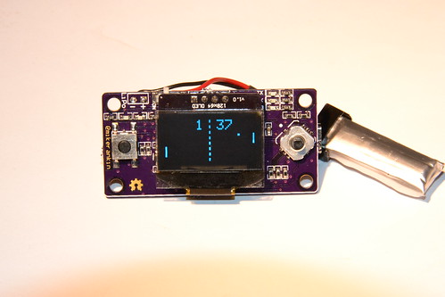
Sensor Board Main display Side Showing Ponglock
Feature list:
- I2C Bus to save pins for future use.
- 128×64 OLED I2C Display: let’s draw anything
- Momentary switch on left and cross plus center buttons on right (total 6 input buttons)
- Arduino Leonardo based: USB for anything.
- Temperature sensor (I2C)
- Barometer sensor (I2C)
- Accelerometer sensor (I2C)
- Real Time Clock (I2C) plus backup battery.
- Switched power supply.
- LiPo charger.
- Tiny design: let’s make portable projects.
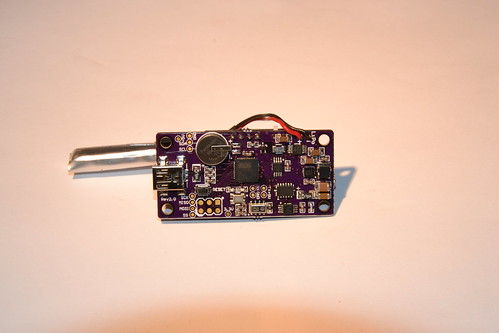
Sensor Board Main Component Side
I couldn’t resist temptation.. I ported the pongclock code from Rob Parrett to this tiny board. Here is the result:
Hardware is open hardware, you can obtain anything on Mike’s web or you can buy it directly from Tindie. Custom pongclock code can be downloaded from here.
Update: I fixed 3 bugs in the original code to fix pong game behavior to be as accurate as possible, like the scoreboard, ball missing and properly change of hours.
Publicado el 6th Junio, 2013 por KaRMaN. Archivado en Arduino, Electrónica.
Leido 313,116 veces. 10 comentarios archivados.
Update: If you want one for real it is now for sale at Mike’s Tindie page
here.
Update 2: I made a 3D printed enclosure for this hardaware. You can find more
here.
About 9 months ago one Hackaday reader dropped some comments about compiling the source I published here a year ago and some troubles. After that, Mike and me kept talking and things turn out that he was PCB developer, so we though we could make together GPS cube version for real.
Together we developed a schematic and Mike built all himself several prototypes until we finally came with a (almost!) final version. So, here we are, one year after first release:
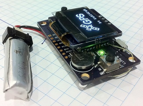
GPS Cube version 2
This version has several features:
- Everything is packed together in a single board.
- Better GPS: we switched to MT3339 PA6H instead old SirfStar III EM-411
- We added TMP75 I2C temperature sensor.
- The display PCB is also custom to run 3.3v
- Everything runs 3.3v: GPS, display, FTDI, TMP75 and atmega328p is now running 8MHz, Battery lasts longer.
- Expansion header with SPI and I2C: the board ca be used as development board for any other projects with displays or GPS.
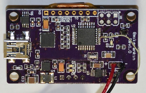
GPS Toy Hardware Rev1.0
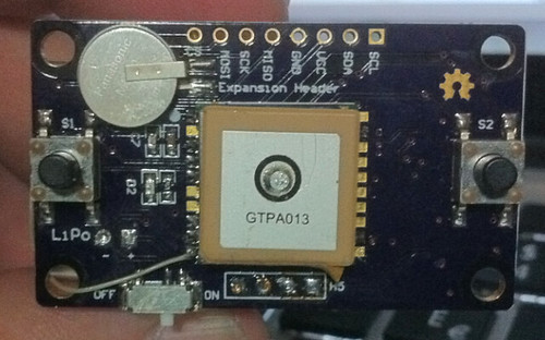
New GPS Board back
All the hardware was designed and developed by Mike Rankin (probably will go to Tindie) meanwhile I developed the software.
Publicado el 30th Mayo, 2013 por KaRMaN. Archivado en Cacharros, Electrónica.
Leido 111,436 veces. 1 comentario archivado.
.. and couldn’t resist to tear it down >:3
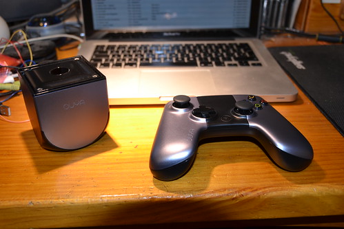
Ouya Video Game System
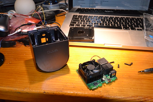
Ouya Teardown
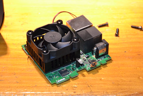
Ouya main board
It’s body is metal built. It gives the console a robust appearance but the WiFi antenna is damn small, so the console is pretty much signal-deaf. Also the case air flow is bad: the console may heat up. I think basing it’s main OS on top of android is a bad idea, as android can (and is) heavy, leaving less resources to games. Also case is almost empty, not well used space.
BUT, is open source and hackable :)
Publicado el 8th Abril, 2013 por KaRMaN. Archivado en Sin categoria.
Leido 11,211 veces. Comments Off
This is a very small tube display usually mounted as a camcorder viewfinder. Can work by powering it with 8v and composite signal input.
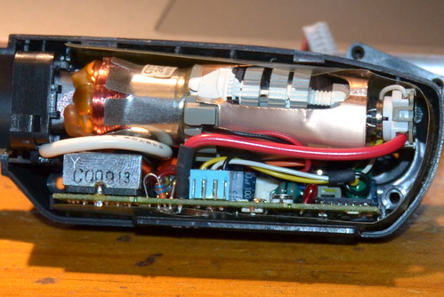
Small tube display viewfinder


