Archivos en la categoría 'Hardware'

Arduino Enigma Portable

Jueves, Enero 11th, 2018

I recently got an Arduino Enigma on Tinder (https://www.tindie.com/products/ArduinoEnigma/arduino-enigma-i-m3-m4-machine-simulator-w-case/) which is a Arduino Enigma Machine Simulator with touch display. Is pretty handsome with a wooden case and perfectly functioning simulator of the Enigmas 1, M3 and M4.

But to work, it needs external power supply. Either a USB-B cable or a 9v battery with a barrel plug. And I hate having external addons to make it work.

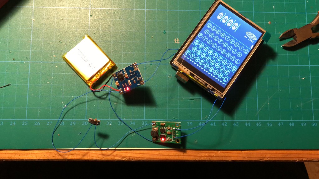
Arduino Enigma Machine with battery

Arduino Enigma Machine with battery

So I put inside the case a lipo battery, a lipo charger and a 5v stepup to power up everything.

ZTE680 Hardware V4.0 (V2?) Hack

Domingo, Agosto 20th, 2017

I just got recently installed my first FTTH router (pepephone, but same model is used in masmovil and jazztel) and as any network engineer I wanted to have full access to the router. Looking over the vast internet I found a blogpost that used a USB with a symlink to smb.conf so it can be edited to add exec parameters to execute an downloaded busybox to open an alternative telnetd but the article had a big problem that make it imposible to work on my router: the F680 of the article has an ARM architecture. My router has MIPS instead. This is important to know beforehand if using external-downloaded busybox binaries. In the end I skipped the busybox hack to directly allow admin telnet connection instead the buggy limited one. This is how I did it, I will assume that router has IP address 192.168.1.1.

(más…)

Expired RSA SecurID Token revival (guerrilla hack)

Lunes, Enero 25th, 2016

I had lying around an expired RSA SecurID with the typical blank display only showing a small 3 in the right.

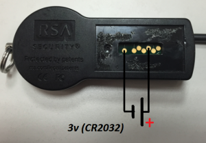
Looking for some info about expired tokens I found an old topic at flickr (original URL here) where Travis Goodspeed managed to revive one the tokens with a simple trick: apply 3v for a second in two of the pads behind the protective plate.

Here is the diagram:

Expired RSA SecurID Token Revival Diagram

Expired RSA SecurID Token Revival Diagram

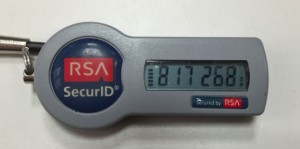
Here the revived Token:

Expired RSA SecurID Token Revived

Expired RSA SecurID Token Revived

The token was expired since november 2011 but still got battery to keep working.

I Haven’t tested if token still is valid to autenticate against RSA daemon after revival.

GPS Toy / On board computer

Martes, Junio 5th, 2012
Update: This hardware was made from parts at adafruit, sparkfun and dealextreme. See the new, custom design with more power efficiency, better GPS and temperature sensor here.

This is something I’ve been working about a month now. It’s a little handheld GPS / on board computer that shows altitude, current course, synced satellites, speed, time and date, distance between saved point and current point (and its course and corrdinates) and total trip distance.
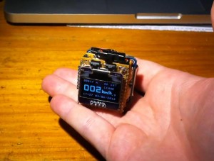
Cube GPS Toy

Cube GPS Toy

At first I wanted a speed-o-meter for my bike but you know, coding it’s free and could stop adding functions.

I managed to get some cheap serial GPS receptor, a tiny OLED display and an Arduino Mini Pro and started to code. First I knew I would need some big font and so I made my own using paint, each character 24×32 (96bytes). This is the complete parts list:

  • Ebay I2C SSD1306 based OLED display, 128×64, 0.96″ and 5V.
  • Ebay Arduino Mini Pro (ATMEGA328p), 5V 16Mhz
  • Sparkfun DC-DC step-up voltage converter (5V).
  • Adafruit MPC73833 LiPo battery charger.
  • Savaged iPod Nano 1st gen battery.
  • Dealextreme EM-411 GPS 5V receiver.
  • Savaged momentary buttons, resistors and wires.

I had to code some method to print own big fonts in the display and the moment I managed to control all the display functions as I wanted I started to code the methods to print GPS gathered data in the display. This is an earlier slowed display test that didn’t worked well:

The first prototype had just speed mode, was assembled with double tape and had no battery charger. It’s purpose was to see how speed meter worked testing it in my car.
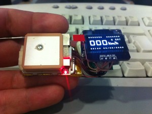
First handheld GPS prototype

First handheld GPS prototype

Then I dismantled firts prototype and assembled second prototype, this time no double tape, just boards soldered togheter. This is the schematic:

Tiny GPS schematic

Tiny GPS schematic

And so I began building:
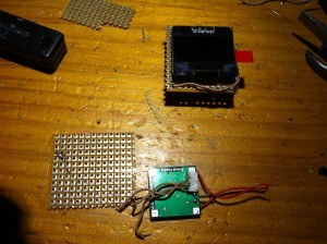
OLED Display up, GPS Conector (glued to DC-DC) down.
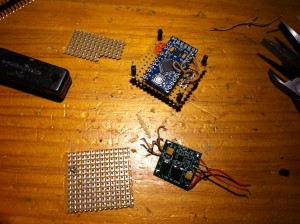
OLED Display up, GPS Conector (glued to DC-DC) down.

Second prototype assembling. Arduino Up, DC-DC down.

Second prototype assembling. Arduino Up, DC-DC down.

The actual prototype looks like a tiny packed devices cube with front display and momentary switches (best view on 720p). Here is a video with functions explanation:

I’m not a coder so code is pretty much ugly. Sketch it’s downloable from here. It uses TinyGPS library from Mikal Hart, custom new software serial to disable interrupts in pin ports and PinChangeInt, an Arduino library to handle buttons interrupts.

If you would like to contribute with functions or code fixes please feel free to contact me either in the comments or in my email address (at the bottom of the page).
Poken Teardown

Viernes, Noviembre 11th, 2011

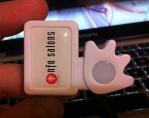
Pequeño recuerdo de la feria UFI #78 celebrada estos días en Valencia. No había participante que no tuviera uno.

The Poken Out of the Box.

The Poken Out of the Box.

Se trata de un juguete tecnológico que intenta ser el reemplazo de las clásicas tarjetas de visita por tarjetas de visita digitales. Para que dos personas intercambien sus tarjetas de visita solamente han de juntar sus pokens y luego acudir al servicio web con el poken conectado al ordenador.

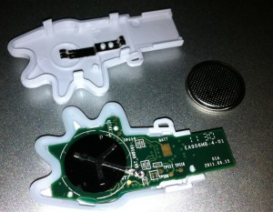
Poken open in two parts for battery change.

Poken open in two parts for battery change.

El Poken puede desmontarse en dos parte sin mucho problema, probablemente para cambiar la batería. Está cerrado por una serie de clips de plástico que salen con cierta facilidad aplicando un poco de fuerza con un destornillador plano. Se cierra con la misma facilidad. Al iniciarse el circuito el LED del centro de la mano se ilumina parpadeando tres veces, indicando que el Poken está listo.

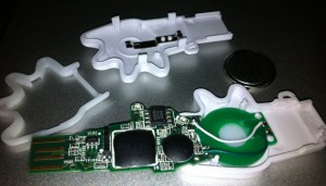
Poken Teardown

Poken Teardown

El circuito está sujeto a la mitad que contiene la antena por 3 puntos de plástico fundido. Una vez limados, el circuito sale facilmente mostrando la cara superior del mismo y la antena a la que va soldada, que es el PCB verde redorno que está a la derecha del mismo, unido con dos cables.

En el circuito principal se pueden apreciar 3 chips: dos de ellos en formato de gota de plástico y el tercero en forma de DIP de 4 patillas. Este último es una memoria EEPROM de 64K. Según las especificaciones el poken guarda hasta 64 contactos por lo que imagino que la ID que intercambia tiene un peso de 1K.

Por lo demás, es un cacharrito curioso :D